Unstructured Meshes#
Concepts#
The conservation element and solution element (CESE) method is developed against the set-up of unstructured meshes in multi-dimensional space Mavriplis [Mav97] Wang and Chang [WC99]. In contrast to structured meshes, unstructured meshes allow flexible connectivity and simplex elements. The implementation, i.e., the data structures and the computer code for their algorithms, of unstructured meshes dictate how simulation software operates. It serves two purposes: numerical methods for simulation and mesh generation.
Geometry#
Cells are the discrete volume for the space of interest. Faces are the interface between two cells. Nodes represent the coordinates in space. A mesh is also a Voronoi diagram, and the “cell” is a Voronoi cell [BCKO10].
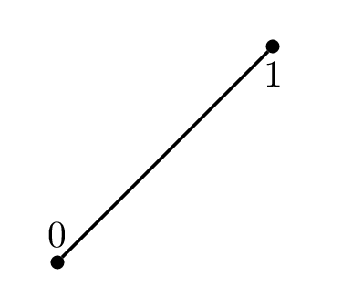
Fig. 1 Line (type number 1).#
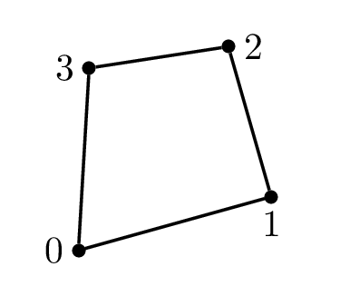
Fig. 2 Quadrilateral (type number 2).#
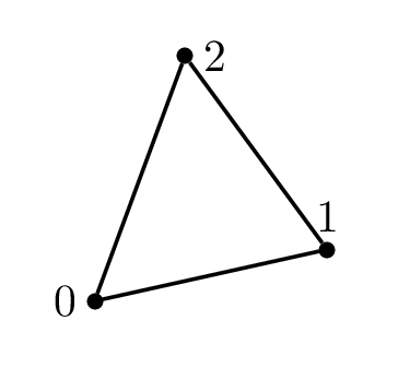
Fig. 3 Triangle (type number 3).#
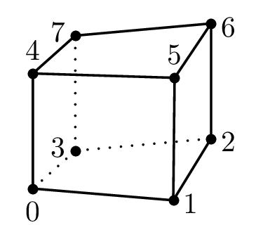
Fig. 4 Hexahedron (type number 4).#
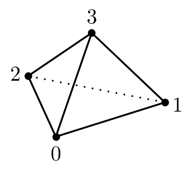
Fig. 5 Tetrahedron (type number 5).#
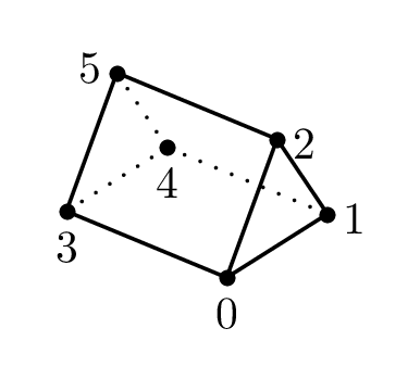
Fig. 6 Prism (type number 6).#
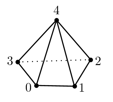
Fig. 7 Pyramid (type number 7).#
Data Store#
Most operations on meshes done by the simulation are reading. The mesh is usually assumed to be constant. Numerical methods may use moving meshes, but it is an advanced topic that should be treated separately.
The code uses a set of lookup tables to store the unstructured mesh. The technique is commonly seen in unstructured-mesh solvers for the efficient memory use. The CESE method is finite-volume-based and associates variables with volume centers. The data store optimizes for easily reading values for discrete volume, and thus defines cell, face, and node.
The code allows mixing elements of different shapes. The mesh definition data are listed in the following tables and figures.
Element Metadata#
Name |
Type |
Dimension |
Points |
Lines |
Surfaces |
|---|---|---|---|---|---|
Point |
0 |
0 |
1 |
0 |
0 |
Line |
1 |
1 |
2 |
0 |
0 |
Quadrilateral |
2 |
2 |
4 |
4 |
0 |
Triangle |
3 |
2 |
3 |
3 |
0 |
Hexahedron |
4 |
3 |
8 |
12 |
6 |
Tetrahedron |
5 |
3 |
4 |
6 |
4 |
Prism |
6 |
3 |
6 |
9 |
5 |
Pyramid |
7 |
3 |
5 |
8 |
5 |
One-Dimensional Sub-Entities#
Shape (type) |
Face |
= Node |
|---|---|---|
Line (1) |
0 |
0 |
1 |
1 |
Two-Dimensional Sub-Entities#
Both of two-dimensional elements are enclosed by straight lines.
Shape (type) |
Face |
= Line formed by nodes |
|---|---|---|
Quadrilateral (2) |
0 |
\(\diagup\) 0 1 |
1 |
\(\diagup\) 1 2 |
|
2 |
\(\diagup\) 2 3 |
|
3 |
\(\diagup\) 3 0 |
|
Triangle (3) |
0 |
\(\diagup\) 0 1 |
1 |
\(\diagup\) 1 2 |
|
2 |
\(\diagup\) 2 0 |
Three-Dimensional Sub-Entities#
Three-dimensional elements are enclosed by triangles or quadrilaterals, or a combination of them. \(\square\) denotes quadrilaterals, while \(\triangle\) denotes triangles. Nodes are ordered so that the normal vector of a surface points outward from the volume by following right-hand rule.
Shape (type) |
Face |
= Surface formed by nodes |
|---|---|---|
Hexahedron (4) |
0 |
\(\square\) 0 3 2 1 |
1 |
\(\square\) 1 2 6 5 |
|
2 |
\(\square\) 4 5 6 7 |
|
3 |
\(\square\) 0 4 7 3 |
|
4 |
\(\square\) 0 1 5 4 |
|
5 |
\(\square\) 2 3 7 6 |
|
Tetrahedron (5) |
0 |
\(\triangle\) 0 2 1 |
1 |
\(\triangle\) 0 1 3 |
|
2 |
\(\triangle\) 0 3 2 |
|
3 |
\(\triangle\) 1 2 3 |
|
Prism (6) |
0 |
\(\triangle\) 0 1 2 |
1 |
\(\triangle\) 3 5 4 |
|
2 |
\(\square\) 0 3 4 1 |
|
3 |
\(\square\) 0 2 5 3 |
|
4 |
\(\square\) 1 4 5 2 |
|
Pyramid (7) |
0 |
\(\triangle\) 0 4 3 |
1 |
\(\triangle\) 1 4 0 |
|
2 |
\(\triangle\) 2 4 1 |
|
3 |
\(\triangle\) 3 4 2 |
|
4 |
\(\square\) 0 3 2 1 |